IB DP Physics · Theme B · The particulate nature of matter

Current and circuits.

B.5 · Charge, current and potential difference, resistance, circuits, and cells with internal resistance
Standard level and higher level

The journey

Four parts.

Part 01

Current and potential difference

Charge carriers, cells and circuit diagrams

Part 02

Resistance and power

Ohm’s law, resistivity and the heating effect

Part 03

Series and parallel

Combining resistors, and the potential divider

Part 04

Real cells and sensors

Internal resistance, thermistors, LDRs and potentiometers

B.5 CURRENT AND CIRCUITS · SL + HL

Part 01

Current and potential difference.

What flows round a circuit, and what makes it flow

B.5 CURRENT AND CIRCUITS · SL + HL

The story · Italy, 1800

Background story · not assessed

Volta builds the first battery.

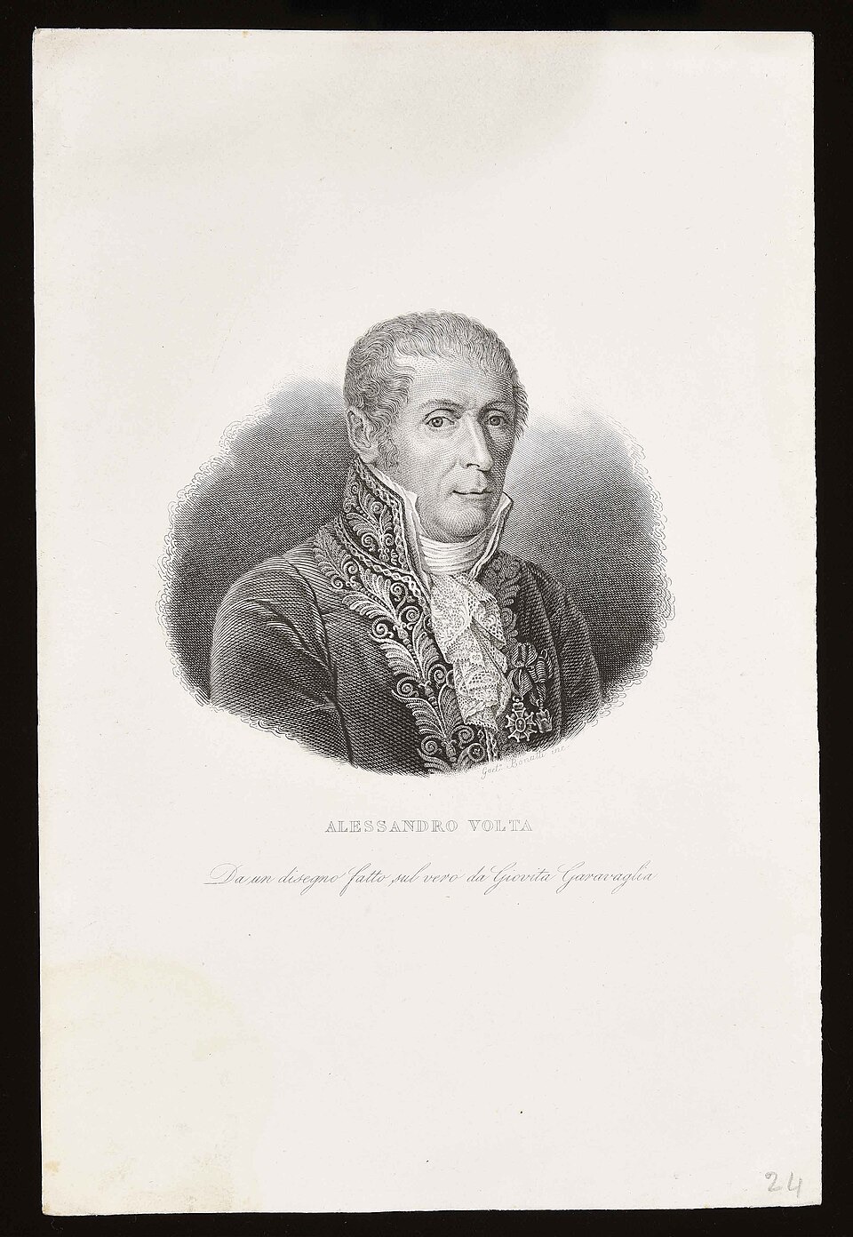
Engraved portrait of Alessandro Volta, a man in a high-collared coat
Alessandro Volta, engraved in 1837
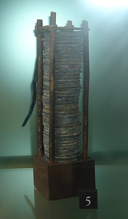
A tall stack of metal disks held upright between four thin rods on a wooden base, in a museum case
A voltaic pile in the Tempio Voltiano, Como
  • Luigi Galvani had made frogs’ legs twitch with two metals. He and Volta argued over why
  • Volta stacked disks of zinc and copper (or silver), separated by cloth soaked in brine
  • 20 March 1800: he describes it in a letter to the Royal Society
  • Within months it was used to split water into hydrogen and oxygen
The first source of a continuous current. Every circuit starts here.

Portrait: Gaetano Bonatti, 1837, CC0. Photograph: GuidoB, CC BY-SA 3.0 (cropped).

B.5 CURRENT AND CIRCUITS · SL + HL

A flow of charge carriers

Electric current.

\(I = \dfrac{\Delta q}{\Delta t}\)
  • Unit: the ampere, \(1 \,\mathrm{A} = 1 \,\mathrm{C} \,\mathrm{s}^{-1}\)
  • In a metal the carriers are free electrons
  • Conventional current: from + to −, opposite to the electrons
INSIDE A METAL WIRE
B.5 CURRENT AND CIRCUITS · SL + HL

Mobility of charge carriers

Conductors and insulators.

Conductor

Many carriers, free to move

A metal: about one free electron for every atom, moving through the whole solid

Insulator

Carriers bound in place

Plastic, glass, dry air: the electrons are held to their atoms

In between

A few carriers, set free by energy

Semiconductors such as silicon: heat or light frees more carriers

What matters is how many charge carriers there are and how freely they can move.
B.5 CURRENT AND CIRCUITS · SL + HL

Energy per unit charge

Potential difference.

\(V = \dfrac{W}{q}\)
  • The work done per unit charge in moving a positive charge between two points
  • Unit: the volt, \(1 \,\mathrm{V} = 1 \,\mathrm{J} \,\mathrm{C}^{-1}\)
  • Always between two points: “across” a component
A lamp with 6.0 V across it carries 0.25 A for 2.0 minutes \(\Delta q = I \Delta t = 0.25 \times 120 = \class{res}{30 \,\mathrm{C}}\) \(W = qV = 30 \times 6.0 = \class{res}{180 \,\mathrm{J}}\) Number of electrons \(N = \dfrac{\Delta q}{e} = \dfrac{30}{1.60 \times 10^{-19}} = \class{res}{1.9 \times 10^{20}}\)
B.5 CURRENT AND CIRCUITS · SL + HL

Where the energy comes from

Cells as sources of emf.

  • A cell does work on charge: its emf is the energy it supplies to each coulomb, in volts
Chemical cellSolar (photovoltaic) cell
Energy fromA chemical reaction inside the cellLight falling on a semiconductor
ForPortable; works anywhere, at any time; steady emfNo fuel and nothing emitted in use; lasts for decades
AgainstRuns down; limited energy stored; materials must be mined and recycledOutput depends on the light: none at night; low emf per cell, so many are joined in series; little power from each square meter, so large areas are needed
B.5 CURRENT AND CIRCUITS · SL + HL

Circuit diagrams

Circuit symbols.

AS IN THE DATA BOOKLETTHE LONGER LINE OF A CELL IS POSITIVE
or Both mean resistor. Many textbooks use the zigzag symbol.
B.5 CURRENT AND CIRCUITS · SL + HL

Quick check

Current and potential difference.

0112 C passes a point in 4.0 s. Current?

3.0 A

02Which way do electrons move, compared with conventional current?

The opposite way

0360 J is transferred when 5.0 C passes through a heater. Potential difference?

12 V

04What is one volt in terms of joules and coulombs?

1 J C⁻¹

05What makes a metal a good conductor?

Many free electrons

06Give one disadvantage of a solar cell.

No output in the dark
PRESS → TO REVEAL EACH ANSWER

Part 02

Resistance and power.

How hard it is to drive a current, and what that costs in energy

B.5 CURRENT AND CIRCUITS · SL + HL

Opposition to current

Resistance.

\(R = \dfrac{V}{I}\)
  • Unit: the ohm, \(1 \,\Omega = 1 \,\mathrm{V} \,\mathrm{A}^{-1}\)
  • The equation defines resistance, for any component
  • Origin: drifting electrons collide with the vibrating ions of the metal
  • Each collision passes energy to the ions: the wire gets hot
  • Hotter metal: the ions vibrate more, so more resistance
B.5 CURRENT AND CIRCUITS · SL + HL

The story · Cologne, 1827

Background story · not assessed

A schoolteacher’s law.

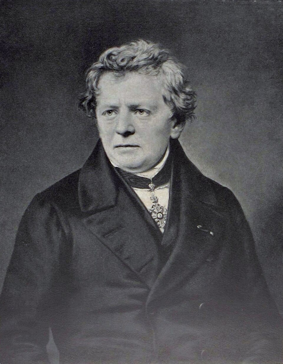
Portrait of Georg Ohm, an older man with white hair in a dark coat
Georg Simon Ohm
  • Ohm taught mathematics and physics at a school in Cologne, and built his own apparatus
  • He tested wires of different lengths and found how the current depended on them
  • 1827: he published his law in The Galvanic Circuit Investigated Mathematically
  • It was coldly received. He resigned his post
  • 1841: the Royal Society awarded him its Copley Medal
A professor at last, in Munich, in 1852: two years before he died.

Portrait: unknown artist, public domain.

B.5 CURRENT AND CIRCUITS · SL + HL

Ohmic and non-ohmic behavior

Ohm’s law.

  • For a metal at constant temperature: \(I \propto V\)
  • Ohmic: constant resistance, a straight line through the origin
  • A filament lamp is non-ohmic: it heats up, and its resistance rises
OHMIC
FILAMENT LAMP
B.5 CURRENT AND CIRCUITS · SL + HL

The material, not the object

Resistivity.

\(\rho = \dfrac{RA}{L}\)
  • So \(R = \dfrac{\rho L}{A}\): longer means more resistance, thicker means less
  • Unit: \(\Omega \,\mathrm{m}\)
  • A property of the material at a given temperature
Material at 20 °C (approximate)ρ / Ω m
Copper\(1.7 \times 10^{-8}\)
Aluminum\(2.8 \times 10^{-8}\)
Nichrome (heating wire)\(1.1 \times 10^{-6}\)
Silicon\(\sim 10^{3}\)
Glass\(\sim 10^{12}\)
B.5 CURRENT AND CIRCUITS · SL + HL

Worked example

A length of copper cable.

20 m of copper wire, diameter 1.0 mm · \(\rho = 1.7 \times 10^{-8} \,\Omega \,\mathrm{m}\) \(A = \pi r^{2} = \pi \times (0.50 \times 10^{-3})^{2}\) \(A = 7.9 \times 10^{-7} \,\mathrm{m}^{2}\) \(R = \dfrac{\rho L}{A} = \dfrac{1.7 \times 10^{-8} \times 20}{7.9 \times 10^{-7}}\) \(R = \class{res}{0.43 \,\Omega}\)
  • Twice the diameter: four times the area, so a quarter of the resistance
  • The same wire in nichrome: \(\dfrac{1.1 \times 10^{-6}}{1.7 \times 10^{-8}} = 65\) times as much, 28 Ω
B.5 CURRENT AND CIRCUITS · SL + HL

The heating effect

Electrical power.

\(P = IV = I^{2} R = \dfrac{V^{2}}{R}\)
  • The rate at which energy is transferred in a component
  • In a resistor, all of it becomes thermal energy

Always

\(P = IV\)

Coulombs per second × joules per coulomb

When you know the current

\(P = I^{2} R\)

Components in series; losses in cables

When you know the p.d.

\(P = \frac{V^{2}}{R}\)

Components in parallel; appliances on the mains

B.5 CURRENT AND CIRCUITS · SL + HL

Worked example

A kettle and its cable.

A 2.0 kW kettle on a 230 V supply \(I = \dfrac{P}{V} = \dfrac{2.0 \times 10^{3}}{230} = \class{res}{8.7 \,\mathrm{A}}\) \(R = \dfrac{V^{2}}{P} = \dfrac{230^{2}}{2.0 \times 10^{3}} = \class{res}{26 \,\Omega}\)
Its cable has a resistance of 0.10 Ω \(P_\mathrm{cable} = I^{2} R = 8.7^{2} \times 0.10\) \(P_\mathrm{cable} = \class{res}{7.6 \,\mathrm{W}}\) Under 0.5% of the power: it stays cool
B.5 CURRENT AND CIRCUITS · SL + HL

Quick check

Resistance and power.

01A resistor carries 0.20 A with 9.0 V across it. Resistance?

45 Ω

02What does the \(I\)–\(V\) graph of an ohmic conductor look like?

A straight line through the origin

03Why does the resistance of a filament rise as it heats?

The ions vibrate more: more collisions

04A wire is stretched to twice its length with the same volume. Resistance?

Four times: twice \(L\), half \(A\)

05Power in a 10 Ω resistor carrying 3.0 A?

\(3.0^{2} \times 10 = 90 \,\mathrm{W}\)

06What is the unit of resistivity?

Ω m
PRESS → TO REVEAL EACH ANSWER

Part 03

Series and parallel.

Two ways to join components, and two conservation laws that explain them

B.5 CURRENT AND CIRCUITS · SL + HL

One path

Resistors in series.

\(I = I_{1} = I_{2} = \dots\) \(V = V_{1} + V_{2} + \dots\) \(R_\mathrm{s} = R_{1} + R_{2} + \dots\)
The total is larger than the largest resistor.
IN SERIES
B.5 CURRENT AND CIRCUITS · SL + HL

More than one path

Resistors in parallel.

\(V = V_{1} = V_{2} = \dots\) \(I = I_{1} + I_{2} + \dots\) \(\dfrac{1}{R_\mathrm{p}} = \dfrac{1}{R_{1}} + \dfrac{1}{R_{2}} + \dots\)
The total is smaller than the smallest resistor.
IN PARALLEL
B.5 CURRENT AND CIRCUITS · SL + HL

Worked example

A combination.

The parallel pair \(\dfrac{1}{R_\mathrm{p}} = \dfrac{1}{4.0} + \dfrac{1}{12} = \dfrac{4}{12}\)  so  \(R_\mathrm{p} = 3.0 \,\Omega\) The whole circuit \(R = 6.0 + 3.0 = 9.0 \,\Omega\) \(I = \dfrac{V}{R} = \dfrac{9.0}{9.0} = \class{res}{1.0 \,\mathrm{A}}\) Across the pair \(V_\mathrm{p} = I R_\mathrm{p} = 1.0 \times 3.0 = \class{res}{3.0 \,\mathrm{V}}\)
THREE RESISTORS
B.5 CURRENT AND CIRCUITS · SL + HL

Sharing a potential difference

The potential divider.

The same current in both resistors \(I = \dfrac{V_\mathrm{in}}{R_{1} + R_{2}}\) \(V_\mathrm{out} = I R_{2}\) \(V_\mathrm{out} = \class{res}{\dfrac{R_{2}}{R_{1} + R_{2}} V_\mathrm{in}}\)
Each resistor takes a share in proportion to its resistance.
TWO RESISTORS IN SERIES
B.5 CURRENT AND CIRCUITS · SL + HL

Measuring without disturbing

Ammeters and voltmeters.

  • Ammeter: in series, so that the current passes through it
  • Ideal ammeter: zero resistance
  • Voltmeter: in parallel, across the component
  • Ideal voltmeter: infinite resistance
WHERE THE METERS GO
B.5 CURRENT AND CIRCUITS · SL + HL

Quick check

Series and parallel.

0110 Ω and 15 Ω in series. Total?

25 Ω

02Two 10 Ω resistors in parallel. Total?

5.0 Ω

033.0 Ω and 6.0 Ω in parallel. Total?

\(\frac{3.0 \times 6.0}{9.0} = 2.0 \,\Omega\)

04Which conservation law explains why currents add at a junction?

Conservation of charge

052.0 kΩ above 4.0 kΩ across 12 V. P.d. across the 4.0 kΩ?

\(\frac{4.0}{6.0} \times 12 = 8.0 \,\mathrm{V}\)

06How is a voltmeter connected, and what is its ideal resistance?

In parallel; infinite
PRESS → TO REVEAL EACH ANSWER

Part 04

Real cells and sensors.

A cell with resistance of its own, and resistors that respond to the world

B.5 CURRENT AND CIRCUITS · SL + HL

A real cell

Emf and internal resistance.

\(\varepsilon = I(R + r)\)
  • \(r\): the resistance of the cell itself
  • Terminal p.d.: \(V = \varepsilon - Ir\)
  • \(Ir\): the “lost volts”, dissipated inside the cell
AN IDEAL CELL IN SERIES WITH r
B.5 CURRENT AND CIRCUITS · SL + HL

Worked example

A cell and a lamp.

\(\varepsilon = 1.5 \,\mathrm{V}\) · \(r = 0.50 \,\Omega\) · lamp \(R = 2.5 \,\Omega\) \(\varepsilon = I(R + r)\)  so  \(I = \dfrac{\varepsilon}{R + r}\) \(I = \dfrac{1.5}{2.5 + 0.50} = \class{res}{0.50 \,\mathrm{A}}\) \(V = IR = 0.50 \times 2.5 = \class{res}{1.25 \,\mathrm{V}}\) Lost volts \(= Ir = 0.50 \times 0.50 = 0.25 \,\mathrm{V}\)
Where the power goes Cell supplies: \(\varepsilon I = 1.5 \times 0.50 = 0.75 \,\mathrm{W}\) Lamp: \(I^{2} R = 0.50^{2} \times 2.5 = 0.625 \,\mathrm{W}\) Inside the cell: \(I^{2} r = 0.50^{2} \times 0.50 = 0.125 \,\mathrm{W}\)
B.5 CURRENT AND CIRCUITS · SL + HL

From a graph

Measuring emf and internal resistance.

\(V = \varepsilon - Ir\)
  • Vary the external resistance; record \(V\) and \(I\)
  • A straight line: compare with \(y = c + mx\)
  • Intercept = \(\varepsilon\)
  • Gradient = \(-r\)
TERMINAL P.D. AGAINST CURRENT
B.5 CURRENT AND CIRCUITS · SL + HL

Resistance that changes

Thermistors and LDRs.

  • Thermistor: hotter, lower resistance
  • LDR: brighter, lower resistance
  • Both are semiconductors: energy frees more charge carriers
  • Neither is ohmic
TWO SENSORS
B.5 CURRENT AND CIRCUITS · SL + HL

Worked example

A thermistor in a potential divider.

\(V_\mathrm{in} = 6.0 \,\mathrm{V}\) · \(R_{2} = 10 \,\mathrm{k}\Omega\) · thermistor \(R_{1}\) \(V_\mathrm{out} = \dfrac{R_{2}}{R_{1} + R_{2}} V_\mathrm{in}\) Cold: \(R_{1} = 5.0 \,\mathrm{k}\Omega\) \(V_\mathrm{out} = \dfrac{10}{5.0 + 10} \times 6.0 = \class{res}{4.0 \,\mathrm{V}}\) Hot: \(R_{1} = 1.0 \,\mathrm{k}\Omega\) \(V_\mathrm{out} = \dfrac{10}{1.0 + 10} \times 6.0 = \class{res}{5.5 \,\mathrm{V}}\)
THERMISTOR ABOVE, FIXED RESISTOR BELOW
B.5 CURRENT AND CIRCUITS · SL + HL

A variable potential divider

The potentiometer.

  • One resistor with a sliding contact
  • The contact divides it into two parts, \(R_{1}\) and \(R_{2}\)
  • Moving it changes \(V_\mathrm{out}\) smoothly, from 0 to \(V_\mathrm{in}\)
Volume controls and dimmers are potentiometers.
THREE TERMINALS
B.5 CURRENT AND CIRCUITS · SL + HL

Quick check

Real cells and sensors.

01A cell of emf 6.0 V and \(r\) = 1.0 Ω drives 0.50 A. Terminal p.d.?

\(6.0 - 0.50 \times 1.0 = 5.5 \,\mathrm{V}\)

02When does the terminal p.d. equal the emf?

When no current flows

03On a graph of \(V\) against \(I\) for a cell, what is the gradient?

\(-r\)

04A thermistor is warmed. Its resistance?

It falls

05An LDR is the upper resistor of a divider. It gets dark. The output across the lower resistor?

It falls

06How many terminals of a potentiometer are used in a potential divider?

Three
PRESS → TO REVEAL EACH ANSWER

Summary

Current and circuits on one slide.

Current and p.d.

\(I = \frac{\Delta q}{\Delta t}\) · \(V = \frac{W}{q}\)

Coulombs per second; joules per coulomb

Resistance

\(R = \frac{V}{I}\) · \(\rho = \frac{RA}{L}\)

Ohmic: \(R\) constant at constant temperature

Power

\(P = IV = I^{2} R = \frac{V^{2}}{R}\)

The heating effect of a current

Series

\(R_\mathrm{s} = R_{1} + R_{2}\)

Same current; potential differences add

Parallel

\(\frac{1}{R_\mathrm{p}} = \frac{1}{R_{1}} + \frac{1}{R_{2}}\)

Same potential difference; currents add

Real cell

\(\varepsilon = I(R + r)\)

Terminal p.d. \(V = \varepsilon - Ir\)

B.5 CURRENT AND CIRCUITS · SL + HL

Summary

Key words.

CurrentRate of flow of charge
Potential differenceWork done per unit charge between two points
EmfEnergy supplied per unit charge by a source
ResistanceRatio of potential difference to current
ResistivityThe resistance property of a material
OhmicCurrent proportional to potential difference
Internal resistanceThe resistance of the cell itself
Terminal p.d.What the cell delivers to the circuit: \(\varepsilon - Ir\)
Potential dividerResistors in series sharing a potential difference
B.5 CURRENT AND CIRCUITS · SL + HL